
Installing a TV outdoors is a structural, electrical, and weather-protection task that requires more planning than a standard indoor wall mount. An outdoor audiovisual (AV) installation must be engineered to withstand dynamic environmental loads. These include heavy wind shear, severe diurnal temperature fluctuations, persistent moisture ingress, and the constant threat of electrical grounding failures.
To ensure long-term reliability and safety, an outdoor TV installation must strictly adhere to structural anchoring protocols, utilize GFCI-protected electrical routing, and incorporate an IP65-rated enclosure with properly sized ventilation. This approach protects the sensitive electronic hardware from environmental degradation while securing the heavy asset safely against the architectural structure.
Many catastrophic outdoor TV failures are not caused by defective screens, but by improper installation techniques. Using incorrect masonry anchors, ignoring the physics of water tracking along cables, or failing to account for direct solar loading will guarantee a rapid system failure. In this comprehensive technical guide, we will break down the precise, phased protocols required to mount, power, and protect your outdoor entertainment system safely and securely.
How we evaluate outdoor TV installations at Outvion:
- Structural integrity of the mounting surface and fastener pull-out performance.
- Electrical compliance, including GFCI protection and “drip loop” cable routing.
- Environmental positioning to minimize solar glare and thermal loading.
- Strict adherence to IP65 cable gland sealing protocols
Last Updated: Mar 12th. 2026 | Estimated Reading Time: 9 Minutes
By Smith Chen, Outdoor TV Enclosure Engineer at Outvion.
Phase 1: Site Assessment and Sun Orientation
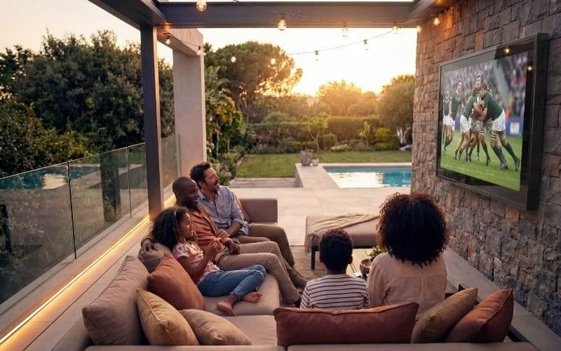
Selecting the correct installation location minimizes thermal and glare risks. Deeply shaded areas, covered patios, or locations protected from prolonged direct afternoon sun are usually the safest choices to reduce thermal strain and improve viewing clarity.
Before drilling a single hole or purchasing mounting hardware, a rigorous site assessment must be conducted. The physical location of the television dictates the required brightness of the display, the necessary structural hardware, and the specific thermal management configuration required for the enclosure.
Evaluating Sun Exposure and Glare
Standard commercial displays are not designed to absorb massive amounts of direct solar radiation. The black plastic bezels and the LCD/OLED panels themselves absorb heat rapidly.
-
The Thermal Risk: Prolonged direct sun exposure can push the internal components past their thermal limits. This solar loading can cause display darkening, image distortion, unexpected shutdown, or permanent panel stress.
-
Orientation Strategy: When planning the installation, orient the screen and mount position carefully. Deeply shaded areas, covered patios, or locations protected from prolonged direct afternoon sun are usually the safest choices.
-
Managing Glare: If partial sun exposure is unavoidable in your chosen location, you must utilize an articulating or tilting VESA mount to angle the screen slightly downward. This deflects the ambient glare toward the floor rather than reflecting it directly into the viewer’s eyes. This scenario also requires sourcing a display with a higher brightness rating (measured in nits) to overpower the ambient outdoor light.
Assessing the Mounting Substrate
The combined weight of a standard commercial display, a heavy-duty articulating mount, and an IP65-rated polycarbonate enclosure can easily exceed 60 to 100 pounds, depending on the screen size.
-
Load-Bearing Requirements: The mounting surface must be structurally sound. Drywall, thin decorative stone veneer, or unsupported vinyl siding cannot support this sustained cantilevered load.
-
Identifying Anchor Points: Installers must locate solid wood studs (typically spaced 16 inches on center in standard residential framing) or assess the integrity of solid concrete, cinderblock, or brick masonry to ensure the fasteners can achieve their required pull-out performance.
Phase 2: Selecting the Proper VESA Mount
The mounting bracket must be rated for the combined weight of the TV and the protective enclosure. When using full-motion mounts, installers must account for the leverage (moment arm) effect, which multiplies the pulling force exerted on the wall anchors.
Once the location is established, selecting the appropriate mounting bracket is the next critical engineering step. Outvion enclosures feature standard VESA (Video Electronics Standards Association) mounting patterns on their exterior rear panels, making them compatible with heavy-duty commercial mounts.
Flat, Tilt, and Full-Motion Mounts
The type of mount you select dramatically impacts the structural forces applied to the wall.
-
Fixed/Flat Mounts: These keep the enclosure flush against the wall. They present the lowest risk of structural failure because the weight acts entirely as downward shear force parallel to the wall surface.
-
Tilt Mounts: These allow the screen to angle downward (typically 10 to 15 degrees). They are highly recommended for outdoor installations to mitigate glare from the sky or overhead patio lights, while still keeping the center of gravity close to the wall.
-
Full-Motion (Articulating) Mounts: These allow the enclosure to be pulled away from the wall and swiveled toward different seating areas.
The Physics of the Moment Arm
If you choose a full-motion articulating mount, you must account for a physics concept known as the “moment arm.”
-
Leverage Forces: When a heavy enclosure is pulled 20 inches away from the wall on an articulating arm, it acts as a lever.
-
Increased Tensile Load: This leverage significantly multiplies the tensile force (the outward pulling force) exerted on the top wall anchors. A 75-pound enclosure extended fully on an arm can exert hundreds of pounds of pull-out force on the masonry anchors or lag bolts.
-
Hardware Sourcing: You must ensure that the articulating mount you purchase is explicitly rated by the manufacturer to handle a weight significantly higher than the combined weight of your TV and the enclosure.
Phase 3: Masonry and Structural Anchoring
Hanging heavy AV equipment outdoors requires specialized, weather-resistant structural fasteners. Installers must drive lag bolts into wood studs or utilize expanding metal anchors for solid masonry walls to achieve better pull-out performance when installed correctly.
The mechanical bond between the wall mount and the architectural structure is the single point of failure preventing your investment from falling. Outdoor environments introduce dynamic forces such as wind shear and ambient vibration, requiring extremely robust anchoring strategies.
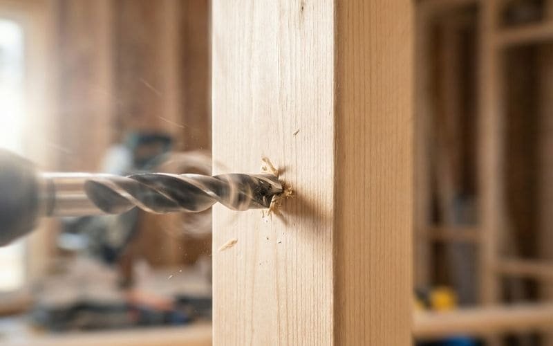
Anchoring into Wood Studs
When mounting to a wood-framed exterior wall (even if it is covered by vinyl siding, hardie board, or stucco), you must anchor directly into the structural wooden studs beneath the facade.
-
Locating the Studs: Use a high-quality electronic stud finder to locate the exact center of the wooden studs.
-
Pilot Holes: Always drill a pilot hole slightly smaller than the diameter of your lag bolt. This prevents the wooden stud from splitting and failing when the thick bolt is driven in.
-
Hardware Selection: Use heavy-duty, exterior-grade stainless steel or hot-dipped galvanized lag bolts (typically 5/16″ or 3/8″ diameter and at least 2.5″ to 3″ long). Do not use standard indoor zinc-plated screws, as outdoor humidity will cause them to rust and corrode, eventually snapping under the shear load.
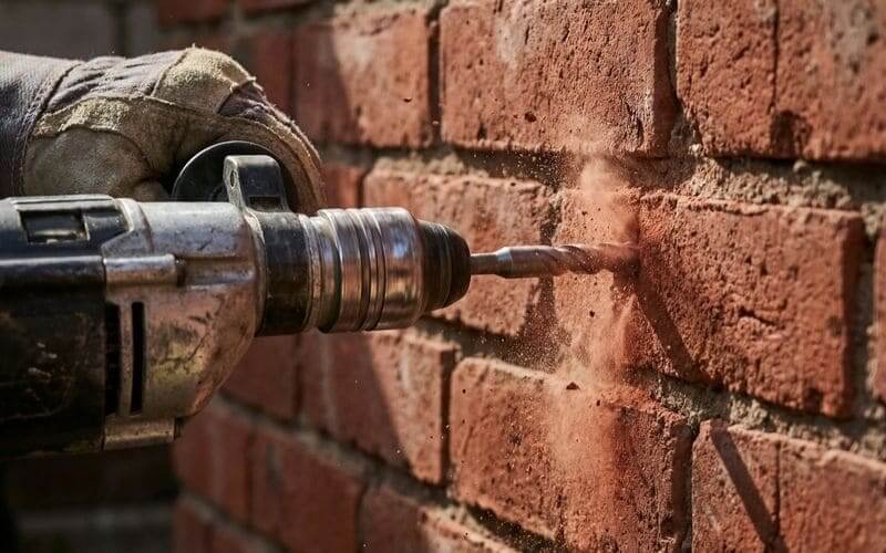
Anchoring into Masonry (Brick, Concrete, Block)
Masonry installations require a completely different approach, relying on mechanical expansion and friction to secure the load against the concrete.
-
Choosing the Right Anchor: Plastic wall plugs are insufficient for heavy cantilevered loads outdoors. Installers must use metal expansion anchors, such as sleeve anchors or wedge anchors, specifically rated for concrete or solid brick.
-
Drilling Protocol: Use a hammer drill with a masonry bit sized exactly to the anchor manufacturer’s specifications. Drill into the solid brick or concrete face, actively avoiding the softer mortar joints between the bricks, as mortar lacks the compressive strength to hold heavy, dynamic loads safely.
-
Clearing the Hole: Before inserting the anchor, use a wire brush and a vacuum to remove all masonry dust from the hole. Residual dust acts as a lubricant and will prevent the metal anchor sleeves from gripping the sides of the hole properly.
Mounting Surface & Hardware Matrix
| Mounting Substrate | Required Hardware | Drilling Protocol | Load-Bearing Reliability |
| Solid Wood Studs | Stainless Steel Lag Bolts (5/16″ or larger) | Drill pilot holes into the exact center of the stud. | Excellent. Highly stable for heavy cantilevered loads. |
| Solid Brick / Concrete | Metal Sleeve or Wedge Anchors | Hammer drill directly into the solid material, avoid mortar. | Excellent. Better pull-out performance when installed correctly. |
| Hollow Cinderblock | Verified Toggle Systems | Hardware selection for hollow block depends on wall condition, load, and mount design; verify with the anchor and mount manufacturer’s guidance. | Variable. Highly dependent on block integrity and face thickness. |
| Drywall / Veneer Only | None | Do not attempt. | Unacceptable. Extreme risk of immediate structural failure. |
Phase 4: Safe Electrical Routing and GFCI Compliance
Powering an outdoor TV requires strict adherence to safety codes to prevent electrical hazards. All outdoor installations must utilize GFCI-protected receptacles and weather-rated “in-use” covers. If local code or the project scope requires it, use a licensed electrician for the outdoor power connection.
Protecting the television hardware is critical, but protecting the facility’s electrical grid and ensuring personal safety is the absolute highest priority. Using a commercial display outside safely requires competent electrical routing that complies with local building and electrical codes (such as the NEC in the United States).
Ground Fault Circuit Interrupter (GFCI) Protection
Water and high-voltage electricity are a lethal combination. Any outdoor electrical receptacle used to power a patio TV or the enclosure’s active fan system must be equipped with GFCI protection.
-
The Mechanism: GFCI devices constantly monitor the current flowing through the hot and neutral wires. If they detect a microscopic imbalance—indicating that current is leaking to ground (such as water interfering with the connection or a person touching a live wire)—the GFCI will instantly cut the power in milliseconds.
-
Compliance: This critical safety feature helps prevent severe electrical shocks and reduces the risk of localized electrical fires caused by moisture-induced short circuits.
In-Use Weather Covers
A standard outdoor outlet cover that features a spring-loaded flat flap is only rated to protect the outlet when nothing is plugged in.
-
Continuous Protection: For an outdoor TV that remains plugged in continuously, you must install a “while-in-use” or “extra-duty” weather cover.
-
The Design: This is a deep, clear or opaque plastic dome that closes completely over the cord and the receptacle. It maintains a weatherproof seal around the outlet even while the thick TV power cord is actively connected to the grid.
Conduit Routing
If you are running new power lines across an exterior wall to reach the TV location, the wires cannot be exposed to the elements or physical damage.
-
Physical Protection: Power must be routed through weather-sealed conduit. Options include rigid PVC conduit or Liquid-Tight Flexible Metallic Conduit (LFMC), depending on the routing requirements and local codes.
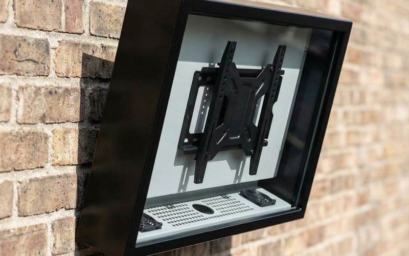
Phase 5: Enclosure Assembly and The Decoupling Strategy
Pairing a standard commercial display with an IP65 enclosure lowers initial CapEx and simplifies future replacements. Installers should mount the empty enclosure backplane to the wall first, then secure the commercial TV inside using the internal VESA mounts to safely manage the hardware weight.
When outfitting a patio or outdoor commercial space, consumers frequently evaluate dedicated “outdoor televisions.” These specialized, all-in-one units feature heavy, integrated weatherproof housings. While durable, they present significant financial and operational drawbacks, as the entire expensive unit must be discarded when the internal screen inevitably fails.
The Financial Logic of Decoupling
The engineered alternative is the hardware decoupling strategy. By separating the rugged protective infrastructure from the digital display, operators gain total control over their AV budget and maintenance timelines.
-
The Strategy: This involves purchasing a heavy-duty, permanent IP65 enclosure and mounting a standard commercial display inside of it.
-
Optimized Pricing: For a 50–55″ setup, Outvion enclosure reference pricing typically starts in the mid-$400s for Basic configurations, with higher-spec Pro or Ultra versions designed for heavier thermal loads priced higher. When combined with a standard commercial display, the total deployment cost is usually much lower than a dedicated outdoor TV setup.
The Phased Assembly Process
To ensure a safe installation, the process must be phased to handle the weight of the components safely.
-
Step 1: Mount the Backplane: Never attempt to lift a fully loaded enclosure onto a wall mount. First, unlock and separate the front polycarbonate bezel from the rear enclosure backplane. Mount the empty, lighter backplane directly to your wall or articulating bracket. Ensure it is perfectly level.
-
Step 2: Internal VESA Mounting: Once the rear shell is securely anchored, lift the standard commercial display into the shell and secure it to the enclosure’s internal VESA mounting rails. Ensure all bolts are hand-tightened to avoid stripping the delicate threads on the TV chassis.
-
Step 3: Preliminary Wiring: Connect the HDMI, optical audio, and power cables to the TV before securing the front cover, allowing enough slack to implement proper sealing protocols.
Weatherproofing Deployment Options & Financial Modeling
| Deployment Strategy | Initial CapEx Burden | Installation Complexity | Long-Term Replacement Cost |
| Standard Commercial Display | Low | Low (Lightweight) | High OpEx due to constant failure in humid environments. |
| Dedicated Outdoor TV | Very High | High (Very heavy integrated unit) | Very High (Requires replacing the entire expensive unit). |
| Enclosure Strategy | Moderate | Moderate (Phased backplane assembly) | Low (Replace internal screen only when needed). |
Pre-Installation Thermal Assessment & Active Airflow Sizing
A completely sealed box creates a thermal trap. To prevent component failure, hotter or more sun-exposed installations require active fan ventilation matched to the internal heat load to flush out waste heat and stabilize the internal micro-climate.
An IP65 enclosure successfully isolates the display from external moisture and insects, but it introduces a secondary engineering challenge: thermal management. An operational television generates internal waste heat from its power supply and backlight array. When combined with external solar loading, the internal temperature can rapidly exceed safe operational thresholds.
Evaluating the Thermal Load
Before locking the front bezel, installers must verify that the enclosure’s ventilation configuration matches the local climate and site exposure.
-
Lower-Heat Zones: In shaded, lower-heat installations (such as deep covered patios in mild climates), lighter-duty configurations may be sufficient.
-
Higher-Heat Zones: However, hotter or more sun-exposed sites should favor ventilated versions. Installations facing partial sunlight or located in warmer geographic regions generate substantial ambient heat, making active forced-air ventilation highly recommended.
Active Airflow Mechanics
To combat elevated thermal loads, operators must utilize active thermal management.
-
The Cooling Mechanism: Ventilated versions use active fan airflow to help remove waste heat from the enclosure cavity, drawing cooler ambient air in through the intakes and exhausting the heated air out.
-
Configuration Sizing: In the current Outvion line, ventilated configurations use 2 fans for 28–55″ models and 4 fans for 60″+ models.
-
Prolonging Hardware Life: This active air exchange helps ensure that the internal micro-climate remains stable, mitigating thermal strain and prolonging the life of the enclosed hardware.
Pre-Installation Thermal Management Matrix
| Installation Environment | Solar Exposure Level | Thermal Risk Assessment | Recommended Ventilation Approach |
| Deep Covered Patio | Minimal direct sunlight | Low Risk | Lighter-duty configurations may be sufficient. |
| Standard Open Deck | Partial afternoon sun | Moderate Risk | Ventilated configurations (2 fans for 28-55″ models). |
| High-Desert / Direct Sun | Intense, direct radiation | High Risk | Pro/Ultra versions with maximum active ventilation (4 fans for 60″+ models). |
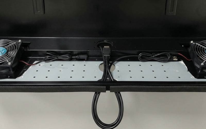
Phase 6: Cable Exit Sealing and Final Inspections
An enclosure is only as weather-resistant as its weakest penetration point. Installers must properly compress the bottom cable glands and implement drip loops; dust, humidity, and insects can bypass the primary seal through the cable exit if a gap is left open.
The final step of the installation is critical for long-term hardware survival. A sealed enclosure cannot protect the internal components if the egress points for the power and data cables are left wide open to the elements.
The Drip Loop Technique
Water travels down cables via gravity and surface tension.
-
The Physics: If a power cord runs straight from the bottom of the TV enclosure directly down into a wall outlet, rainwater will ride that cable like a slide, flowing directly into the electrical socket.
-
The Solution: Installers must always implement a “Drip Loop.” This requires leaving a slack, U-shaped loop of cable that hangs below the level of the wall outlet (and below the enclosure’s cable exit) before curving back up to plug in. When condensation runs down the cable, gravity forces the water to drip harmlessly off onto the ground at the lowest point of the loop.
Sealing the Penetration Points
The physical entry point into the Outvion enclosure must be tightly sealed.
-
Compression Hardware: Outvion utilizes specialized foam blocks or compression glands at the bottom exit points.
-
The Sealing Protocol: During final assembly, technicians must route all cables neatly through these pathways. The foam or rubber grommet must then be tightly compressed around the outer jackets of the wires.
-
Maintaining the Seal: This mechanical pressure creates a tight barrier around the wire. Dust, humidity, and insects can bypass the primary seal through the cable exit if a gap is left open.
Polycarbonate Maintenance SOP
Once the front bezel is locked into place, the structural installation is complete. Installers should leave the homeowner or facility manager with proper cleaning instructions.
-
Prohibited Chemicals: Housekeeping or maintenance staff must never use harsh industrial solvents, acetone, ammonia-based glass cleaners, or abrasive scouring pads on the clear polycarbonate front shield. These will degrade the material and cloud the optical clarity.
-
Approved Methods: Cleaning should be performed exclusively with mild, non-abrasive dish soap, warm water, and clean microfiber cloths.
Conclusion: Ensuring Long-Term Reliability
Installing a television outdoors is an exercise in applied engineering and strict adherence to mechanical protocols. It cannot be achieved safely with improvised wood cabinets, standard drywall anchors, or unprotected indoor extension cords.
By utilizing an engineered IP65-rated physical barrier constructed with optical-grade polycarbonate, you isolate sensitive electronics from the primary threats of moisture ingress, UV degradation, and kinetic impact. Furthermore, by strictly adhering to masonry anchoring protocols, verifying GFCI electrical safety compliance, implementing drip loops, and properly sizing your active thermal ventilation, you can help ensure continuous operational uptime. The decoupling strategy provides the final strategic advantage, ensuring your heavy-duty infrastructure remains a permanent, reliable asset for years to come.
Outdoor Installation FAQ
1. Can I mount the enclosure directly to vinyl siding?
No. Vinyl siding provides zero structural support and will crush under the weight of the mounting bracket. You must locate the structural wooden studs beneath the siding and drive long lag bolts completely through the siding and deep into the solid wood to achieve the necessary shear strength.
2. Do I need to seal the enclosure with silicone caulking?
No. Engineered enclosures use specialized internal gaskets designed to maintain the seal under mechanical compression. Adding aftermarket silicone to the exterior can block intended drainage pathways, fan openings, air paths, and ventilation components, causing moisture retention and severe overheating.
3. How do we manage audio in a noisy outdoor environment?
Because the enclosure is designed to seal out fluids and prevent dust, it naturally dampens the audio output from the TV’s internal, rear-facing speakers. For clearer outdoor audio, plan for an external weather-rated speaker or soundbar during installation, using the TV’s available audio outputs.
4. How quickly can a failed screen be swapped?
The decoupling strategy allows maintenance to unlock the bezel and swap the internal display with substantially less downtime because the enclosure remains installed. Actual replacement time depends on TV size, wiring access, and mount type, but it is vastly faster than uninstalling and remounting a heavy, all-in-one outdoor television.
Recommended Technical Reading & Resources
To further understand the engineering standards and safety protocols discussed in this guide, we recommend reviewing the following authoritative resources:
-
Outdoor Electrical Safety: National Electrical Code (NEC) GFCI Requirements
-
Review the national standards for implementing Ground Fault Circuit Interrupters in wet and outdoor environments to ensure personal and property safety.
-
-
Ingress Protection Standards: IEC 60529: IP Ratings Explained
-
The official international standard defining the testing methodologies for evaluating the degree of protection provided by mechanical casings against dust and water.
-
-
Structural Anchoring Guide: Masonry and Wood Fastener Load Capacities (Simpson Strong-Tie)
-
An engineering resource detailing the shear and tensile strength requirements for safely mounting heavy cantilevered loads to various architectural substrates.
-